Technology
Basic
Principle
and Technology
of the Urbanaut Monorail
![]()
![]()
In This Section
Basic Principle and Technology of the Urbanaut®
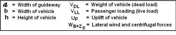
The Urbanaut®vehicles run on top of a narrow guideway that is approximately one-half the width of the vehicle. They are stabilized and locked to the guideway by a uniquely shaped center guide rail on top of the runway; derailment is virtually impossible.
The center guide rail is the primary guidance, and has many functions. It carries concealed power rails and electronic conduits for operation of vehicle and is also used for switching of the vehicle at all speeds.
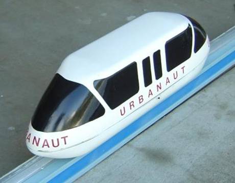
For elevated guideways, a standard, inverted U-Shaped beamway is applied that can bridge long spans between foundations. The cross section is engineered so the beam's inside open space is usable for many functions.
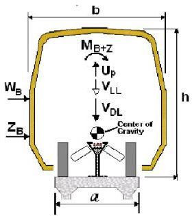
The dynamic forces acting laterally and longitudinally on the Urbanaut® vehicle interact very close to its low center of gravity, which also coincides with the shear center of the beam way.
Such innovative concepts create minimum rotation and moments on the vehicle bogie and the guideway and simplify, to a large degree, the overall monorail system, resulting in a much lighter and simpler vehicle, considerably less cost to install, manufacture and operate and maintain. At surface, on a bridge deck or in a tunnel, only the top slab of the guideway is needed.
In contrast to the straddle type monorail systems, which envelope and are dependent on a large massive beam, the Urbanaut®is considerably smaller and lighter. Its smaller guideway is half or less the width and size of conventional transit and existing maglev systems, a major cost saving in comparison.
Since the vehicle is stabilized by two drive wheels the center rail can be removed in enclosed areas and maintenance facilities and the vehicles then moved at will. This feature further effects the costs positively.
The Urbanaut® is not dependent on a massive beamway as used in the straddle-type monorail systems, which use numerous wheels along the sides of the beamway to stabilize the very tall vehicle. Urbanaut is designed and engineered so that dynamic forces acting laterally and longitudinally on the vehicle interact very close to its low center of gravity (COG).
![]()
The rubber tire Urbanaut® applies high pressure pneumatic noiseless load and guide wheel tires. The tires have run-flat safety inserts to prevent deflation.
The load traction tires are spaced apart to provide additional stability of the vehicle. The inclined guide wheels provide guidance, and prevent overturning, derailment and uplift of the vehicle. They are automatically spring loaded to allow for steeper climbs and stability.
The concept has been extensively tested in the Urbanaut® Monorail Technology Center and other factual applications.
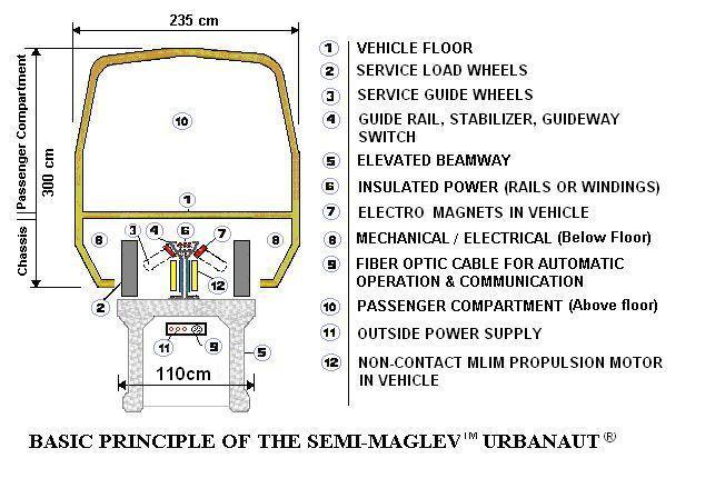
The SemiMaglev™ Urbanaut® applies the same guideway as the rubber tire technology, except electro magnets are provided parallel to the guide wheels. These interact with the magnetic rail over an air gap which partially or fully levitates the vehicle, an alternative which use depends on economics and speed. The MLIM can also be applied as propulsion for the rubber tire system.
SemiMaglev™ Urbanaut® is unique since it operates at low speeds by conventional means, and magnetic levitation is gradually applied as the vehicle picks up speed. At ultra high speeds the vehicle is fully levitated.
![]()
|
Ideal for use with rubber tires and Semi-maglev, a center rail with a uniquely shaped head dynamically guides and stabilizes the vehicle against excessive wind and centrifugal lateral forces. The guide rail head configuration locks the vehicle to the guideway and derailment is virtually impossible. (Patents issued allow for different shapes of the head for guidance.) For stability, the vehicle has a low center of gravity, and exceptionally low aerodynamic and magnetic drag resistances and low ground effect interference. The guideway is approximately half the width of the vehicle. Forces on the vehicle are transferred through a bogie to the guideway below. |
|