Technology
![]()
![]()
In This Section
Train-Passenger Capacities Chart
|
NO. |
LENGTH OF |
NOMINAL |
CRUSH LOADING |
STATION |
||||
|
ONE TRAIN |
ONE TRAIN |
PER HOUR |
PER HOUR |
|||||
|
SEATED |
STANDEE |
SEATED |
STANDEE |
|||||
|
1 |
31.2' |
18 |
25 |
18 |
36 |
2,160 |
4,320 |
16' |
|
2 |
57.2' |
36 |
48 |
36 |
61 |
4,360 |
8,720 |
32' |
|
3 |
79.2' |
58 |
72 |
58 |
102 |
6,400 |
12,8000 |
54' |
|
4 |
101.2' |
78 |
93 |
78 |
137 |
8,600 |
17,200 |
76' |
|
5 |
123.2'
|
98 |
114 |
98 |
172 |
10,800 |
21,600 |
98' |
|
6 |
145.2'
|
118 |
135 |
118 |
207 |
13,000 |
26,000 |
120' |
|
7 |
167.2'
|
138 |
156 |
138 |
242 |
15,200 |
30,400 |
142' |
From the table you can select length of train and station needed to match the passenger capacity. For a dual guideway, the number of potential passengers doubles. The capacity ratio of seated verses standees is based upon arrangement for as many seated passengers as practical.
![]()
|
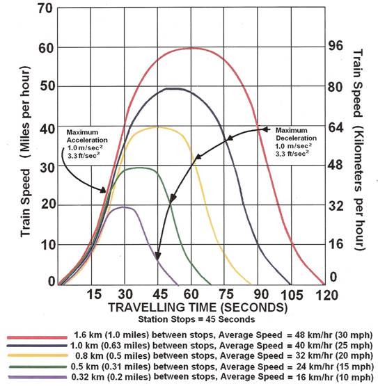
GRAPH I
Urbanaut® v With short distances between stations - 0.8km – yellow curve - the maximum speed shown is 64 km/hr. v For 1.6 km between stations, the maximum speed is 96 km/hr – red curve |
|
|
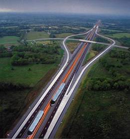
Graph II High Speed Urbanaut® In Median of Freeway
For 9.0 km (5.6) between stations, the maximum speed is 224 km/hr (140 mph) – red curve |
 |
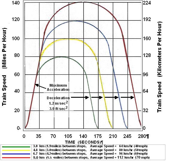
The potential speed of an Urbanaut® is dependent on the distance between station stops.
HIGH SPEED URBANAUT®
MONORAIL
DUAL GUIDEWAY
AT SURFACE IN MEDIAN OF FREEWAY
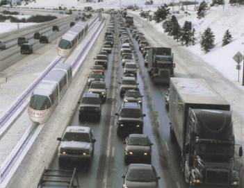
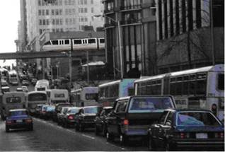
An inexpensive high speed Urbanaut® constructed on a 1.2 meter wide surface guideway in the median of a freeway can favorably compete with autos, thus reducing the congestion, gridlock and pollution on the freeway, and provide a relaxed, stress less ride and a much shorter traveling time at reasonable cost.
Practical and economical speed
The maximum economical speed of 225 km/hr (140 mph) is probably the upper speed for an Urbanaut or high speed rail along our freeways because of the limited right-of-way curvatures. Proposed ultra high speed systems of 310 mph (500 km/hr) require very large radial curves, which would require additional right-of-way along our freeways, and longer distances (20 miles {30km}) between stations, substantially increasing the costs and reducing passenger's service area.
When comparing costs between Urbanaut and high speed or conventional steel wheel/rail technology, all factors effecting costs per passenger and kilometer should be evaluated. In such a cost comparison, the Urbanaut is favored by a large margin. Since the guideway is only 1/3 the size, the aerial requirement is much less and is not dependent on overhead wires at surface and sub-surface.
A High Speed Urbanaut™ with a potential speed of 225 km/hr (140 mph) could, for example, travel from Vancouver BC, Canada to Eugene, Oregon, USA, a distance of 690 km in approximately 4 hours with 1 minute stops in Bellingham, Everett, Seattle, Bellevue, SeaTac Airport, Tacoma, Portland, Salem and Eugene. This is half the time an auto would take driving nonstop with no freeway congestion.
There are numerous other similar application sites along freeways in the USA and abroad. Such an inexpensive high speed Urbanaut® as a back-bone system can have passenger transfers to slower speed Urbanaut® Circulators or distribution networks serving high density communities and cities. Applying the same technology throughout has numerous practical and economical advantages. It becomes more efficient, has greater capacity and is a less costly alternative than complicated tunnel diversions and expensive, massive, outdated steel wheel-steel rail concepts.
![]()
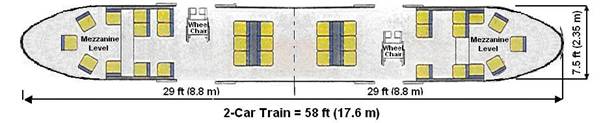
VEHICLE FLOOR PLANS
& ELEVATIONS
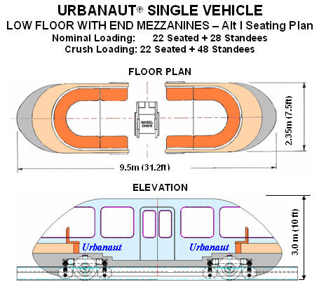
For the Single Vehicle Floor Plan shown,
the seating is around the perimeter of the vehicle,
with standees in the middle of the floor.
Each end has a
step-up to a separated mezzanine level, making the vehicle height only
3.0m.
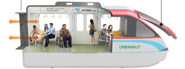
SIDE ELEVATION
ALTERNATIVE FLOOR PLAN
![]()
URBANAUT® 4-CAR HIGH CAPACITY TRAINS
The Urbanaut® System is applicable to trunk lines and as commuter vehicles and for potential large volumes of passenger traffic per hour. It can be made for high speed with longer distances between stops.
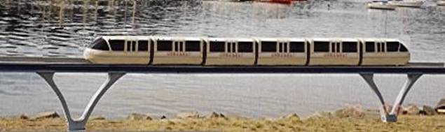
An Intermediate Size Urbanaut® train of 6 cars with a length of 42m (136 ft) has the potential carrying capacity of 26,000 passengers per hour (seated + standees), with a headway of 1½ minutes between trains, when using a dual guideway and station length of 37m (120ft).
![]()
|
|
|
|
Mezzanine End View |
Interior View |
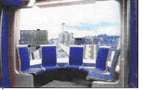
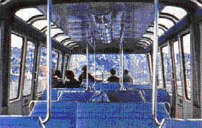
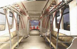
With short distances between station stops, the interior seating plan of the train is flexible. For maximum passenger capacity, seating can be arranged along the sides with standees holding onto interior safety devices
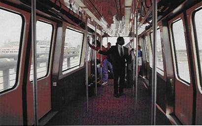
For airport and campus transportation with automatic frequent stops, vehicle interiors can be arranged as shown for easy entry and exit with luggage, with the doors made wider than standard types.
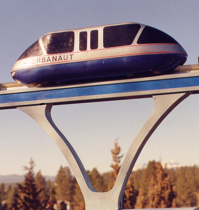
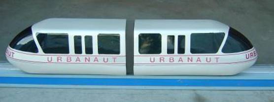
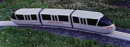
URBANAUT® MONORAIL SMALL SCALE PRT VEHICLES
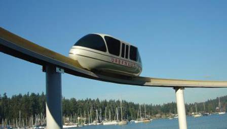
Urbanaut's small, low profile PRT (Personal Rapid Transit) vehicles can operate on smaller, independent guide ways such as "circulators" serving campuses, shopping centers, parks, stadiums, special events and short distance transportation.
In
the Urbanaut®
system, the smaller PRT vehicles can also operate on the regular wider
guide way which enables a PRT vehicle fleet to be diverted to service
large numbers of passengers for a specific purpose on the main line.
The guide way has several simple active and passive switching devices.
The
PRT can operate with short intervals, as single or dual vehicles.
PRACTICAL
APPLICATION OF USING A PRT SINGLE MONORAIL GUIDEWAY LOOP
AS FEEDER LINE FOR HIGH CAPACITY FULL SCALE URBANAUT® TRUNKLINE

![]()

Urbanaut® rotational guideway sweeper – special broom for snow and debris removal
To keep the guideway free of debris and snow, a special electric broom sweeper is used that can be mounted to the front of a vehicle. Such routine maintenance can be done over night or when the guideway is not occupied.
![]()