Technology
![]()
![]()
In This Section
Semi-Maglev EMS Propulsion Technology
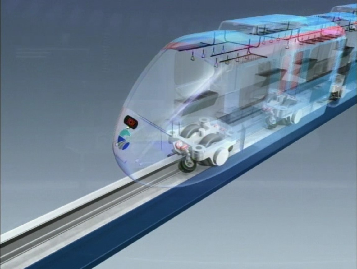
v Each vehicle has 2 light weight bogies, one in front and one at the rear end. Bogies are fabricated of non-magnetic materials like aluminum, stainless steel, and/or composite materials.
v The bogies are the “brain” in the vehicle, and they are the “link” between the vehicle and the runway below
v Bogies support, propel, control and guide the vehicle. A transparency of the vehicle shows how the bogie interacts with the guideway.
v
Alternative I
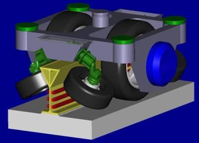
Rubber Tire Wheel Bogie
In-wheel electro magnetic motor in vehicle for speeds up
to 160 km/hr (100 mph)
v
Alternative II
(EMS) Electro Magnetic System with MLIM Propulsion
Maglev linear induction motor
in vehicle for speeds up to 225 km/hr (140mph)
![]()
Alternative I
|
|
|
|
|
A rubber tire wheel bogie makes physical contact with the guideway with the 2 load wheels and 4 guide wheels. The car body above is mounted on top of 2 bogies with connection through a center pivot pin that absorbs lateral and longitudinal forces. The vertical loading from the car body is transferred through the 4 corners of the bogie frame, each with air bag suspension and vehicle leveling devices.
|
Electrical and electronic equipment attached to the bogie automatically controls propulsion, speed, acceleration and deceleration of the vehicle. A powerfull in-wheel direct drive electromagnetic motor is mounted to the side or inside of the 2 load wheels and is powered by a variable-frequency inverter.
|
|

Alternative II
SemiMaglev™ Urbanaut® Propulsion
(EMS) Electro Magnetic System
With MLIM Propulsion - Open Web
The SemiMaglev Urbanaut is unique since it operates by conventional means at low speed, then becomes partially levitated with increasing speed, and fully levitated with no wheel contact at ultra high speed.
v
An MLIM
(Maglev Linear Induction Motor) in the vehicle interacts with the iron
guide rail, with an attached aluminum reaction plate, across an air-gap.
A repulsive force is created between the MLIM and iron guide rail.
The MLIM has no axle, no gear, and no mechanical contacts.
v The MLIM interacts with an inverter installed in the vehicle, which regulates propulsion, speed, braking and control.
v Attractive type electromagnets (EM) levitate (partially or fully) and guide the vehicle along the central rail.
For additional information see the Maglev '04 Proceedings.
![]()